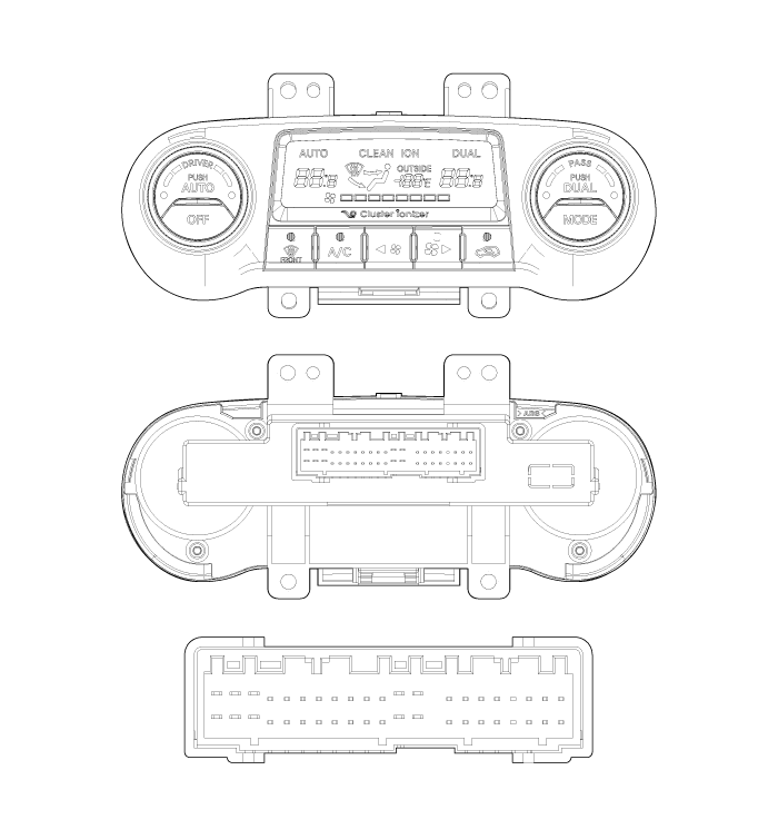
Hyundai Tucson: Controller / Heater & A/C Control Unit(Dual) Components and Components Location
Hyundai Tucson (LM) 2010-2015 Service Manual / Heating, Ventilation and Air Conditioning / Controller / Heater & A/C Control Unit(Dual) Components and Components Location
| Components |
| Control Panel |

Connector Pin Function
| Connector | Pin NO | Function | Connector | Pin NO | Function |
| Connector(A) | 1 | Battery | Connector(B) | 1 | CAN (LOW) |
| 2 | Tail Lamp (ILL+) | 2 | CAN (HIGH) | ||
| 3 | IG2 | 3 | Intake Actuator (F/B) | ||
| 4 | DR Temp Actuator (COOL) | 4 | Mode Actuator (F/B) | ||
| 5 | DR Temp Actuator (WARM) | 5 | PS Temp Actuator (F/B) | ||
| 6 | - | 6 | DR Temp Actuator (F/B) | ||
| 7 | Mode Actuator (VENT) | 7 | Diagnosis (Cluster Ion) | ||
| 8 | Mode Actuator (DEF) | 8 | ECV IN | ||
| 9 | - | 9 | GND | ||
| 10 | - | 10 | Hi-Scan (K-Line) | ||
| 11 | - | 11 | Evaporator Sensor | ||
| 12 | Rheostat (ILL-) | 12 | Ambient Sensor | ||
| 13 | GND | 13 | Incar Sensor | ||
| 14 | Vref +5V | 14 | DR Sun (-) | ||
| 15 | Ion Signal | 15 | PS Sun (-) | ||
| 16 | Intake Actuator (FRE) | 16 | ECV OUT | ||
| 17 | Intake Actuator (REC) | | | ||
| 18 | Clean Signal | | | ||
| 19 | Blower Motor (+) | | | ||
| 20 | PS Temp Actuator (COOL) | | | ||
| 21 | PS Temp Actuator (WARM) | | | ||
| 22 | Power Mosfet (GATE) | | | ||
| 23 | Power Mosfet (DRAIN) | | | ||
| 24 | - | | | ||
| 25 | - | | | ||
| 26 | Sensor GND | | |
 Heater & A/C Control Unit(Manual) Repair procedures
Replacement
1.
Disconnect the negative (-) battery terminal.
2.
Remove the console upper cover (A).
3.
Using the screwdriver, remove the center facia lower cover (A).
4.
Using the ...
 Heater & A/C Control Unit(Dual) Repair procedures
Self Diagnosis
1.
Self-diagnosis process
2.
How to read self-diagnostic code
After the display panel flickers three times every 0.5
second, the corresponding fault code flickers on the setu ...
Other information:
Hyundai Tucson (LM) 2010-2015 Service Manual: Direct Electro Hydraulic Actuator Coupling Components and Components Location
Component Location
1. Transaxle Assembly2. Transfer assembly3. Propeller shaft4. Coupling assembly
Components
1. Coupling assembly2. Input shaft3. Pressure sensor4. Extension wiring5. Oil hydraulic Motor(Actuator)
...
Hyundai Tucson (LM) 2010-2015 Service Manual: Valve Body Components and Components Location
Components Location
1. PCV adjust screw2. Solenoid valve3. Oil temperature sensor4. Accumulator5. Under drive brake (UD/B) pressure flow hole6. Low & reverse brake (LR/B) pressure flow hole
Valve Body Flow
1. To cooler2. From cooler3. Lubrication(rear)4. Overdrive pressure5. Reducing ...
© 2010-2024 www.htmanual.net
