Hyundai Tucson: Smart Key System / Smart Key Diagnostic Repair procedures
Hyundai Tucson (LM) 2010-2015 Service Manual / Body Electrical System / Smart Key System / Smart Key Diagnostic Repair procedures
| Inspection |
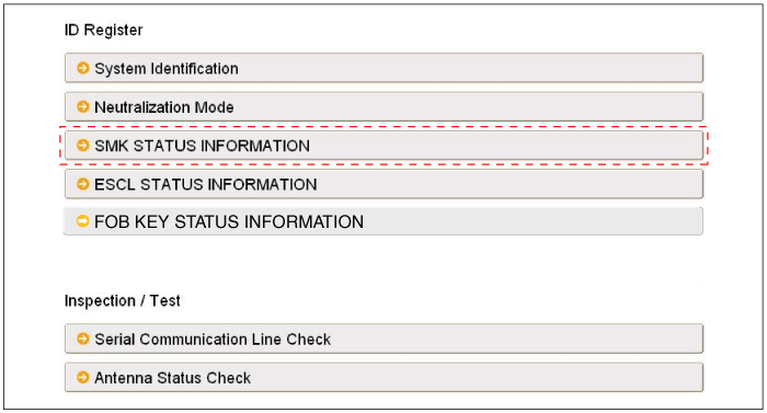
Self Diagnosis With GDS
Smart key system defects can be quickly diagnosed with the
GDS. GDS operates actuator quickly to monitor, input/output value and
self diagnosis.
The following three features will be major problem in SMART KEY system.
| 1. |
Problem in SMART KEY unit input. |
| 2. |
Problem in SMART KEY unit. |
| 3. |
Problem in SMART KEY unit output. |
The following three diagnostic solutions will be the main solution process to a majority of concerns.
| 1. |
SMART KEY unit Input problem : switch diagnosis |
| 2. |
SMART KEY unit problem : communication diagnosis |
| 3. |
SMART KEY unit Output problem : antenna and switch output diagnosis |
Switch Diagnosis
| 1. |
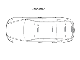
Connect the cable of GDS to the data link connector in driver side crash pad lower panel, turn the power on GDS. |
| 2. |
Select the vehicle model and then SMART KEY system.
|
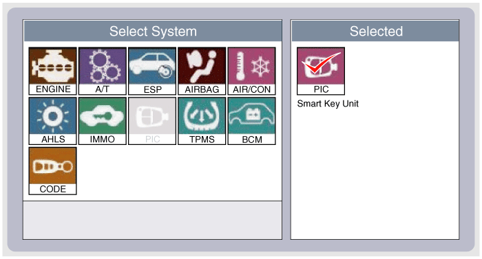
| 3. |
Select the "SMART KEY unit". |
| 4. |
After IG ON, select the "Current data".
|
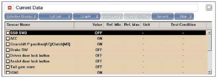
| 5. |
You can see the situation of each switch on scanner after connecting the "current data" process.
|
Communication Diagnosis With GDS (Self Diagnosis)
| 1. |
Communication diagnosis checks that the each linked components operates normal. |
| 2. |
Connect the cable of GDS to the data link connector in driver side crash pad lower panel. |
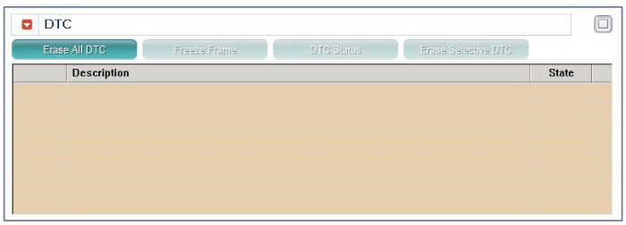
| 3. |
After IG ON, select the "DTC".
|
Antenna Actuation Diagnosis
| 1. |
Connect the cable of GDS to the data link connector in driver side crash pad lower panel. |
| 2. |
After IG ON, select the "ACTUATION TEST".
|
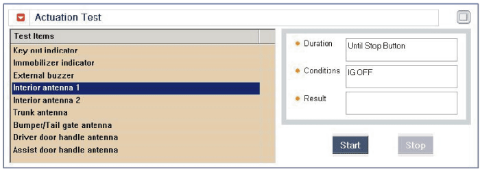
| 3. |
Set the smart key near the related antenna and operate it with a GDS.
|
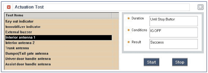
| 4. |
If the LED of smart key is blinking, the smart key is normal. |
| 5. |
If the LED of smart key is not blinking, check the voltage of smart key battery. |
| 6. |
Antenna actuation
|
Antenna Status Check
| 1. |
Connect the cable of GDS to the data link connector in driver side crash pad lower panel. |
| 2. |
Select the "Antenna Status Check".
|
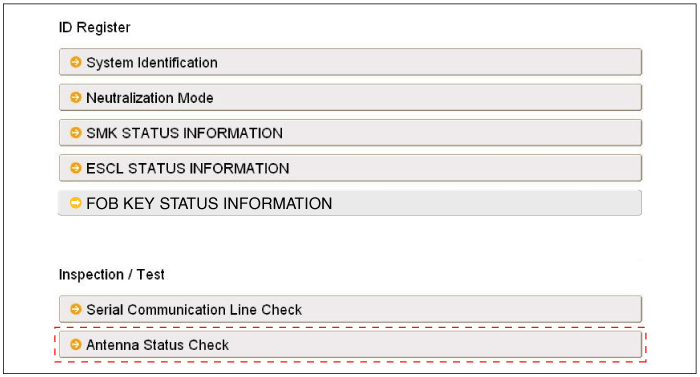
| 3. |
After IG ON, select the "Antenna Status Check".
|
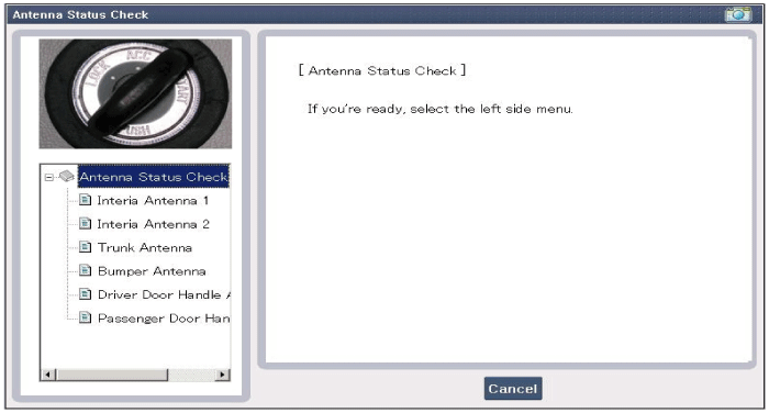
| 4. |
Set the smart key near the related antenna and operate it with a GDS.
|
| 5. |
If the smart key runs normal , the related antenna, smart key(transmission, reception) and exterior receiver are normal. |
| 6. |
Antenna status
|
Serial Communication Status Check
| 1. |
Connect the cable of GDS to the data link connector in driver side crash pad lower panel. |
| 2. |
Select the "Serial Communication Line Check".
|
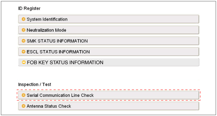
| 3. |
After IGN ON, select the "Receiver Communication Line Check".
|
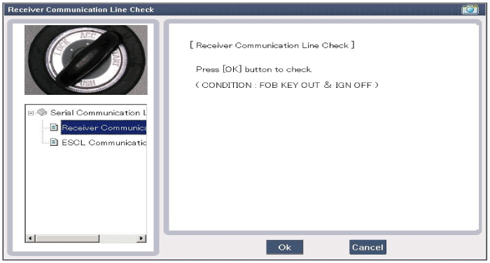
| 4. |
Check the serial communication line with a GDS. |
| 5. |
If the receiver communication line runs normal, check the "ESCL Communication Line Check".
|
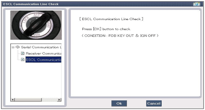
| 6. |
If the smart key runs normal, the communication of smart key unit, exterior receiver and ESCL are normal. |
| 7. |
If the smart key runs abnormal, check the following items.
|
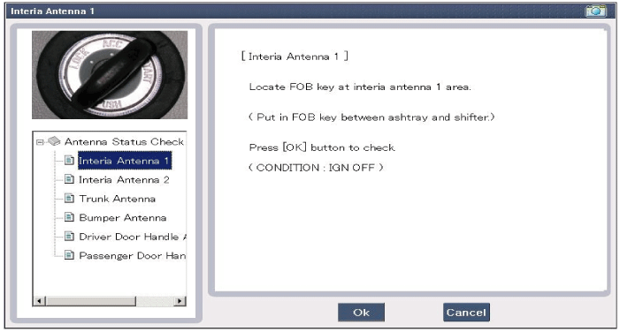
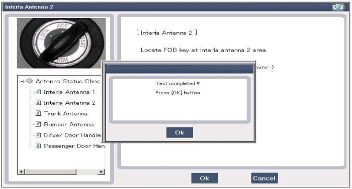
Interior Antenna Actuation Check
| 1. |
Set the smart key in the following shade area and check the IG ON.
|
| 2. |
If the ignition is ON, the antenna runs normal. |
| 3. |
Check the interior antenna ignition mode. |
| 4. |
Set the smart key in the following shade area and actuate the antenna. Check the LED of smart key is blinking.
|
| 5. |
If the LED of smart key is not blinking, check the antenna in shade area.
|
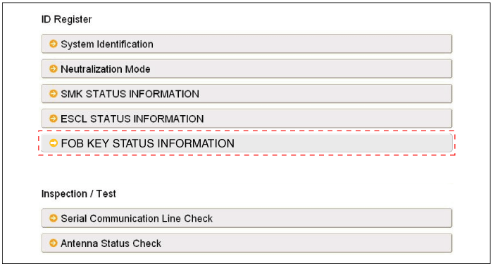
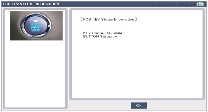
FOB Status Check
| 1. |
Connect the cable of GDS to the data link connector in driver side crash pad lower panel. |
| 2. |
After IGN ON, select the "FOB KEY STATUS INFO".
|
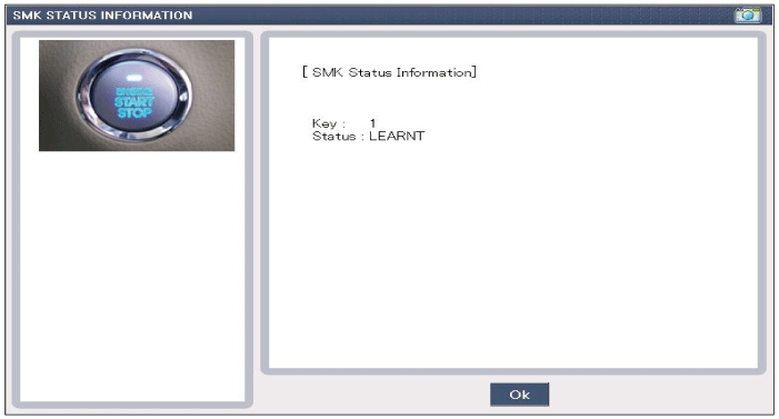
Smart Key Status Check
| 1. |
Connect the cable of GDS to the data link connector in driver side crash pad lower panel. |
| 2. |
After IG ON, select the "SMK STATUS INFO".
|
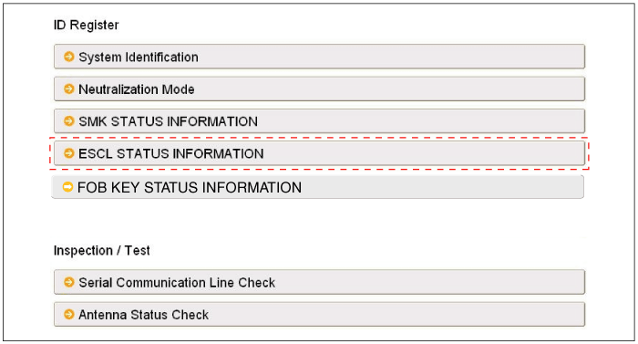
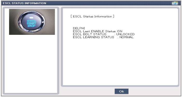
ESCL Status Check
| 1. |
Connect the cable of GDS to the data link connector in driver side crash pad lower panel. |
| 2. |
After IGN ON, select the "ESCL STATUS INFO".
|
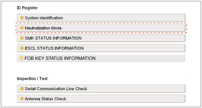
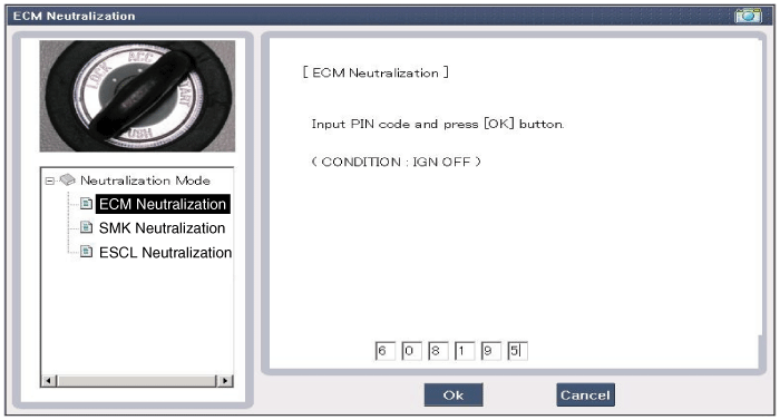
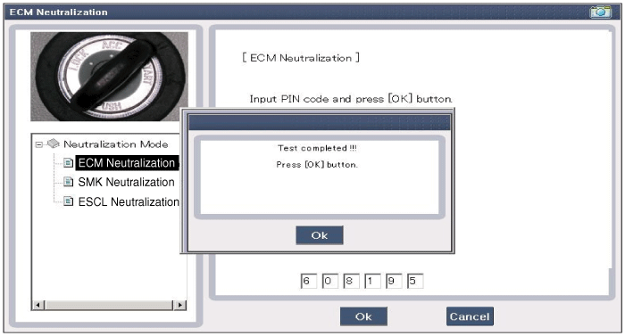
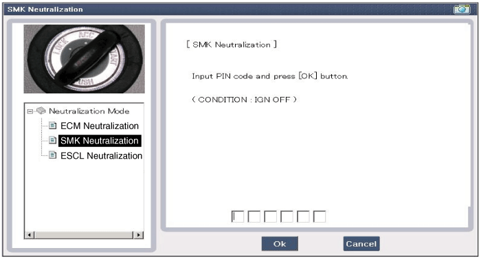
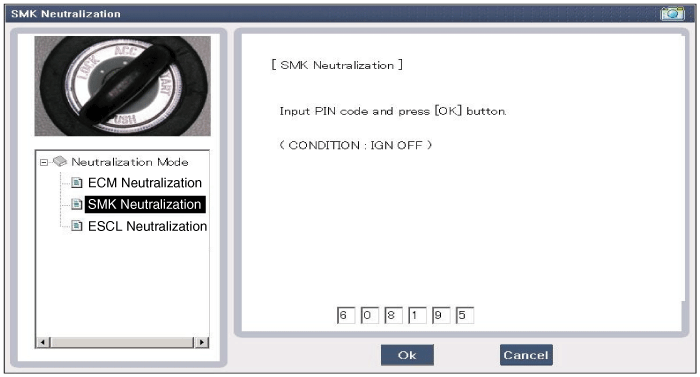
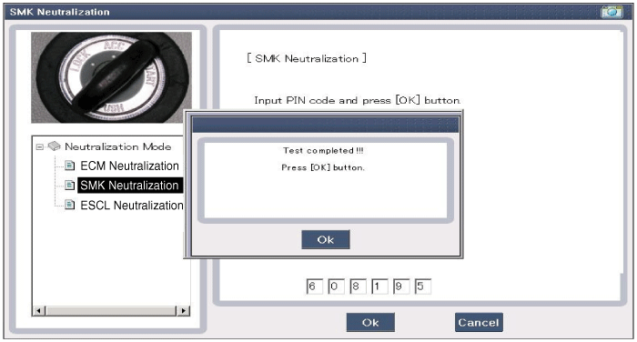
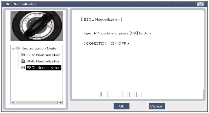
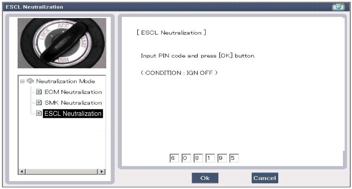
Neutralization Status Check
| 1. |
Connect the cable of GDS to the data link connector in driver side crash pad lower panel. |
| 2. |
After IGN ON, select the "Neutralization mode".
|

Input Switch List
| No | Item name | Unit |
| 1 | SSB switch2 | - |
| 2 | ACC | - |
| 3 | IGN1 | - |
| 4 | Gear 'P' Position | - |
| 5 | Brake switch | - |
| 6 | FL Door Lock Button | - |
| 7 | FR Door Lock Button | - |
| 8 | Trunk Lid switch | - |
| 9 | Battery Voltage | - |
| 10 | Alternator Voltage | - |
| 11 | KEY out Indicator Lamp | - |
| 12 | Immobilizer Lamp | - |
| 13 | External Buzzer | - |
| 14 | ESCL Enable | - |
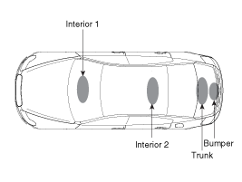
Actuator List
| No. | Item name | Condition |
| 1 | Immo.indicator Lamp | Ignition switch ON Engine off |
| 2 | External Buzzer | Ignition switch ON Engine off |
| 3 | Interior Antenna 1 Active | Ignition switch ON Engine off |
| 4 | Interior Antenna 2 Active | Ignition switch ON Engine off |
| 5 | Trunk Antenna Active | Ignition switch ON Engine off |
| 6 | Bumper Antenna Active | Ignition switch ON Engine off |
| 7 | DRV DR Antenna Active | Ignition switch ON Engine off |
| 8 | AST DR Antenna Active | Ignition switch ON Engine off |
 Smart Key Unit Repair procedures
Removal
Smart Key Unit
1.
Disconnect the negative (-) battery terminal.
2.
Remove the glove box housing.
(Refer to the BD group - "Crash pad")
3.
After disconnecting the smart key unit c ...

Other information:
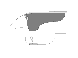
Hyundai Tucson (LM) 2010-2015 Service Manual: Cowl Top Cover Repair procedures
Replacement
1.
Remove the cover and nut, then remove the wiper arm (A).
2.
Detach the clips, then remove the cowl top cover (B).
3.
Install in the reverse order of removal.
•
Replace any damage clips.
...
Hyundai Tucson (LM) 2010-2015 Service Manual: Intake Manifold Repair procedures
Removal and Installation
1.
Remove the engine cover.
2.
Disconnect the battery negative terminal.
Tightening torque:
3.9 ~ 5.9 N.m (0.4 ~ 0.6 kgf.m, 3.0 ~ 4.4 lb-ft)
3.
Disconnect the wiring connectors and harness clamps, and then remove the wiring and protectors from the intake m ...
© 2010-2024 www.htmanual.net
