Hyundai Tucson: Keyless Entry And Burglar Alarm / Repair procedures
Hyundai Tucson (LM) 2010-2015 Service Manual / Body Electrical System / Keyless Entry And Burglar Alarm / Repair procedures
| Inspection |
Front Door Lock Actuator
| 1. |
Remove the front door trim.
(Refer to the BD group - "Front door") |
| 2. |
Remove the front door module.
(Refer to the BD group - "Front door") |
| 3. |
Disconnect the connectors from the actuator.
|
| 4. |
Check actuator operation by connecting power and ground
according to the table. To prevent damage to the actuator, apply battery
voltage only momentarily.
[Central Lock]
[Dead Lock]
|
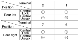
Rear Door Lock Actuator
| 1. |
Remove the rear door trim.
(Refer to the BD group - "Rear door") |
| 2. |
Remove the rear door module.
(Refer to the BD group - "Rear door") |
| 3. |
Disconnect the connectors from the actuator.
|
| 4. |
Check actuator operation by connecting power and ground
according to the table. To prevent damage to the actuator, apply battery
voltage only momentarily.
[Central Lock]
[Dead Lock]
|
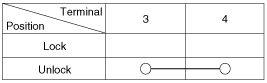
Liftgate Lock Actuator Inspection
| 1. |
Remove the liftgate trim.
(Refer to the BD group - "Liftgate") |
| 2. |
Disconnect the 4P connector from the actuator.
|
| 3. |
Check actuator operation by connecting power and ground
according to the table. To prevent damage to the actuator, apply battery
voltage only momentarily.
|
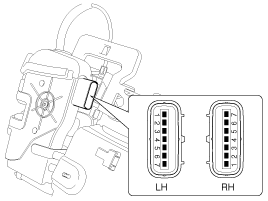
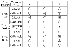
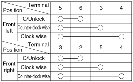
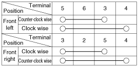
Front Door Lock Switch
| 1. |
Remove the front door trim.
(Refer to the BD group - "Front door") |
| 2. |
Remove the front door module.
(Refer to the BD group - "Front door") |
| 3. |
Disconnect the connectors from the actuator.
|
| 4. |
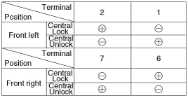
Check for continuity between the terminals in each switch position when inserting the key into the door according to the table.
[Central Lock]
[Dead Lock]
|
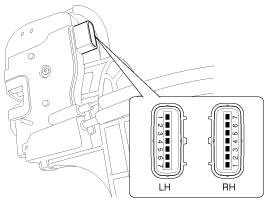
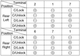
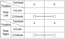
Rear Door Lock Switch
| 1. |
Remove the rear door trim.
(Refer to the BD group - "Rear door") |
| 2. |
Remove the rear door module.
(Refer to the BD group - "Rear door") |
| 3. |
Disconnect the connectors from the actuator.
|
| 4. |
Check for continuity between the terminals in each switch position according to the table.
[Central Lock]
|
Liftgate Switch
| 1. |
Remove the liftgate trim.
(Refer to the BD group - "Liftgate") |
| 2. |
Disconnect the 4P connector from the actuator.
|
| 3. |
Check for continuity between the terminals in each switch position according to the table.
|
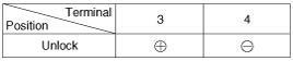
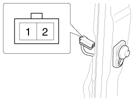
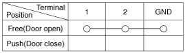
Door Switch
Remove the door switch and check for continuity between the terminals.
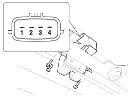
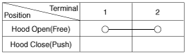
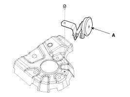
Hood Switch
| 1. |
Disconnect the connector (A) and bolt from the hood switch.
|
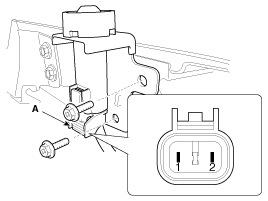
| 2. |
Check for continuity between the terminals and ground according to the table.
|
Burglar Horn
| 1. |
Remove the burglar horn after removing a bolt and disconnect the 2P connector from the burglar horn.
|
| 2. |
Test the burglar horn by connecting battery power to the terminal 1 and ground the terminal 2. |
| 3. |
The burglar horn should make a sound. If the burglar horn fails to make a sound replace it. |
 Description and Operation
Description
Keyless Entry System
The burglar alarm system is integrated with the keyless entry
system. The keyless entry system allows you to lock and unlock the
vehicle with the remote transm ...
 Transmitter Specifications
Specifications
ItemSpecificationRated voltageDC 3VTemperature range-4°F ~ 140°F (-20°C ~ +60°C)RF Modulation methodFSKKeyless entry transmitterPower sourceLithium 3V battery (1EA)Transmissibl ...
Other information:
Hyundai Tucson (LM) 2010-2015 Service Manual: Intake Manifold Components and Components Location
Components
1. Intake manifold assembly 2. Intake manifold gasket3. Electronic throttle body4. Electronic throttle body gasket5. Intake manifold stay
...
Hyundai Tucson (LM) 2010-2015 Service Manual: Alternator Specifications
Specification
Alternator
ItemSpecificationRated voltage13.5V, 120ASpeed in use 1,000 ~ 18,000 rpmVoltage regulatorIC Regulator built-in typeRegulator Setting VoltageExternal mode Refer to below graphInternal mode14.55 ± 0.3V Temperature GradientExternal mode0 ± 3 mV / °CInternal mode-3.5 ± ...
© 2010-2024 www.htmanual.net
