Hyundai Tucson: SRSCM / SRS Control Module (SRSCM) Repair procedures
Hyundai Tucson (LM) 2010-2015 Service Manual / Restraint / SRSCM / SRS Control Module (SRSCM) Repair procedures
| Removal |
| 1. |
Remove the ignition key from the vehicle. |
| 2. |
Disconnect the battery negative cable and wait for at least three minutes before beginning work. |
| 3. |
Disconnect the DAB, PAB, SAB, CAB and BPT connectors. |
| 4. |
Remove the floor console. (Refer to the Body group - console) |
| 5. |
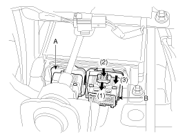
Pull the lock (1) forward and then pull the lever (3) after pressing the lever lock (2).
Disconnect the airbag system control module connector. (A and B)
|
| 6. |
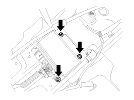
Remove the SRSCM mounting bolts (3EA) from the SRSCM, then remove the SRSCM.
|

| Installation |
| 1. |
Remove the ignition key from the vehicle. |
| 2. |
Disconnect the battery negative cable and wait for at least three minutes before beginning work. |
| 3. |
Install the SRSCM with the SRSCM mounting bolts.
|

| 4. |
Connect the SRSCM harness connector. |
| 5. |
Install the heater ducts and floor console. (Refer to the Body group - console) |
| 6. |
Connect the DAB, PAB, SAB, CAB and BPT connectors. |
| 7. |
Reconnect the battery negative cable. |
| 8. |
After installing the SRSCM, confirm proper system operation:
|
| Variant coding |
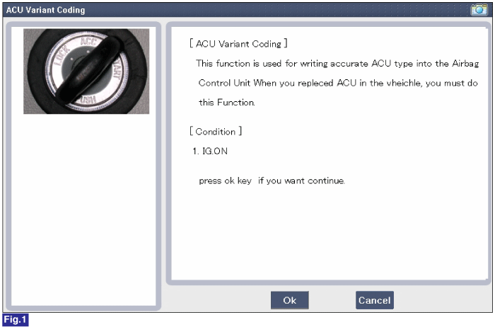
After replacing the SRSCM with a new one, must be performed the “Variant Coding” procedure.
|
Variant coding Procedure
| xnbsp; On-Line type on GDS |
| 1. |
Ignition "OFF", connect GDS. |
| 2. |
Ignition "ON" & Engine "OFF" select vehicle name and airbag system. |
| 3. |
Select Variant coding mode. |
| 4. |
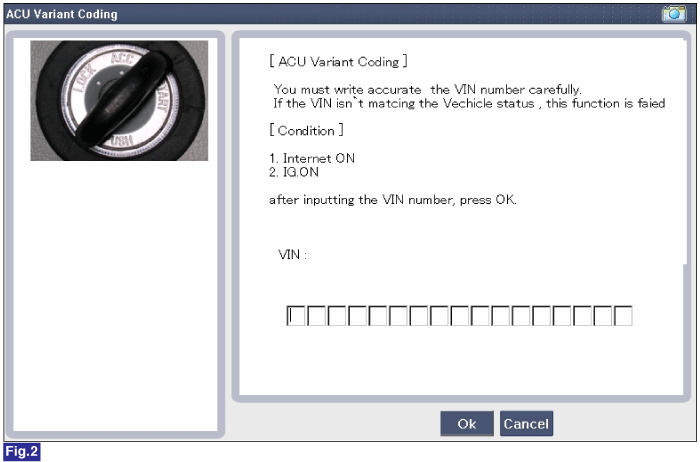
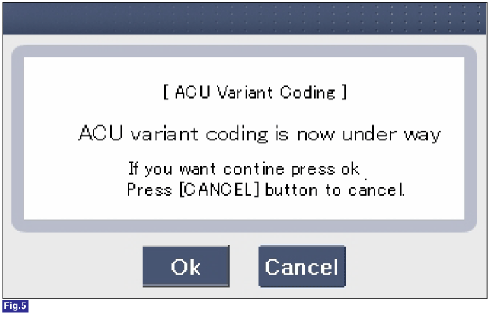
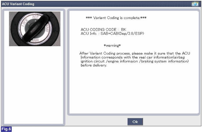
Follow steps on the screen as below. |
1) Initial ACU Variant Coding screen
2) VIN Code entering screen
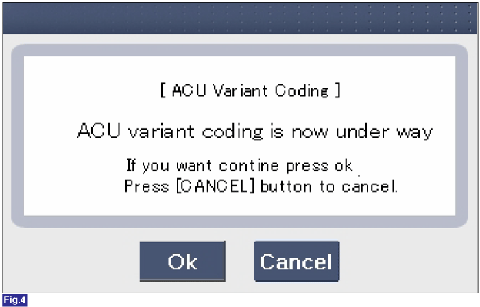
3) Variant coding's proceeding screen-1
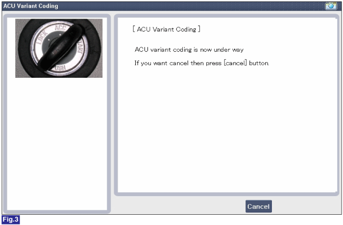
4) Variant coding's proceeding screen-2
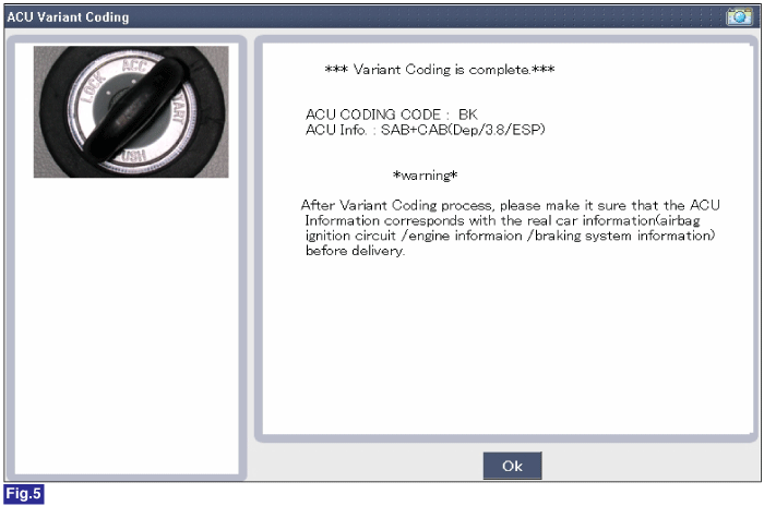
5) Variant coding is completed
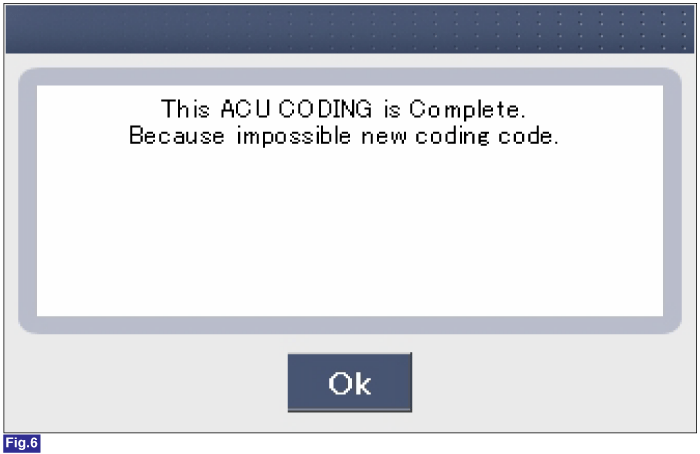
1) This screen is opened when you try the variant coding again on the SRSCM which has bee performed variant coding.
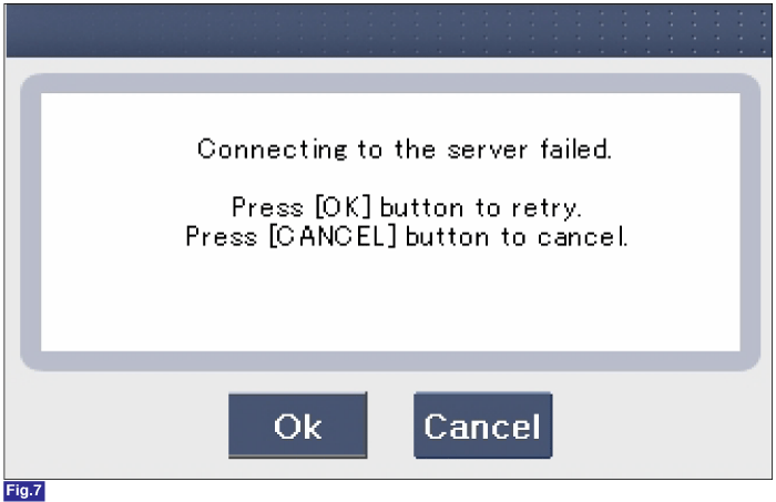
2) Screen of communication failure
|
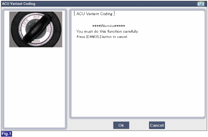
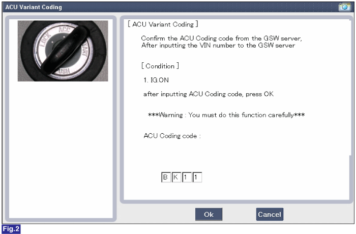
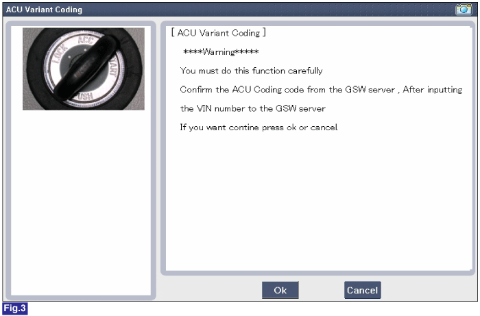
xnbsp; Off-line type on GDS (This can be used when not connecting to internet)
1) Initial ACU Variant Coding screen
2) ACU Coding Code entering screen
3) Screen of rechecking ACU Coding code's entering
4) Variant coding's proceeding screen-1

5) Variant coding's proceeding screen-2
6) Variant coding is completed
1) This screen is opened when you try the variant coding again on the SRSCM which has bee performed variant coding.
|


 Front Impact Sensor (FIS) Description and Operation
Description
The front impact sensor (FIS) is installed in the Front End
Module (FEM). They are remote sensors that detect acceleration due to a
collision at its mounting location. The primary p ...
Other information:
Hyundai Tucson (LM) 2010-2015 Service Manual: Fuel Filler Cap Description and Operation
Description
A ratchet tightening device on the threaded fuel filler cap
reduces the chances of incorrect installation, which seals the fuel
filler. After the gasket on the fuel filler cap and the filler neck
flange contact each other, the ratchet produces a loud clicking noise
indicating ...
Hyundai Tucson (LM) 2010-2015 Service Manual: Components and Components Location
Component Location
1. Power door mirror2. Power door mirror switch3. Power folding mirror switch
...
© 2010-2024 www.htmanual.net
