Hyundai Tucson: Engine Control System / Description and Operation
Hyundai Tucson (LM) 2010-2015 Service Manual / Engine Control / Fuel System / Engine Control System / Description and Operation
| OBD-II review |
1. Overview
The California Air Resources Board (CARB) began regulation of
On Board Diagnostics (OBD) for vehicles sold in California beginning
with the 1988 model year. The first phase, OBD-I, required monitoring of
the fuel metering system, Exhaust Gas Recirculation (EGR) system and
additional emission related components. The Malfunction Indicator Lamp
(MIL) was required to light and alert the driver of the fault and the
need for repair of the emission control system. Associated with the MIL
was a fault code or Diagnostic Trouble Code (DTC) idenfying the specific
area of the fault.
The OBD system was proposed by CARB to improve air quality by
identifying vehicle exceeding emission standards. Passage of the
Federal Clean Air Act Amendments in 1990 has also prompted the
Environmental Protection Agency (EPA) to develop On Board Diagnostic
requirements. CARB OBD-II regulations were followed until 1999 when the
federal regulations were used.
The OBD-II system meets government regulations by monitoring
the emission control system. When a system or component exceeds emission
threshold or a component operates outside tolerance, a DTC will be
stored and the MIL illuminated.
The diagnostic executive is a computer program in the Engine
Control Module (ECM) or PowertrainControl Module (PCM) that coordinates
the OBD-II self-monitoring system. This program controls all the
monitors and interactions, DTC and MIL operation, freeze frame data and
scan tool interface.
Freeze frame data describes stored engine conditions, such as
state of the engine, state of fuel control, spark, RPM, load and warm
status at the point the first fault is detected. Previously stored
conditions will be replaced only if a fuel or misfire fault is detected.
This data is accessible with the scan tool to assist in repairing the
vehicle.
The center of the OBD-II system is a microprocessor called the Engine Control Module (ECM) or Powertrain Control Module(PCM).
The ECM or PCM receives input from sensors and other
electronic components (switches, relays, and others) based on
information received and programmed into its memory (keep alive random
access memory, and others), the ECM or PCM generates output signals to
control various relays, solenoids and actuators.
2. Configuration of hardware and related terms
1) GST (Generic scan tool)
2) MIL (Malfunction indication lamp) - MIL activity by transistor
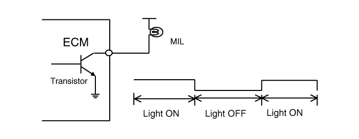
The Malfunction Indicator Lamp (MIL) is connected between ECM
or PCM-terminal Malfunction Indicator Lamp and battery supply (open
collector amplifier).
In most cars, the MIL will be installed in the instrument panel. The lamp amplifier can not be damaged by a short circuit.
Lamps with a power dissipation much greater than total
dissipation of the MIL and lamp in the tester may cause a fault
indication.
x At ignition ON and engine revolution (RPM)< MIN. RPM, the MIL is switched ON for an optical check by the driver.
3) MIL illumination
When the ECM or PCM detects a malfunction related emission
during the first driving cycle, the DTC and engine data are stored in
the freeze frame memory. The MIL is illuminated only when the ECM or PCM
detects the same malfunction related to the DTC in two consecutive
driving cycles.
4) MIL elimination
| • |
Misfire and Fuel System Malfunctions:
For misfire or fuel system malfunctions, the MIL may be
eliminated if the same fault does not reoccur during monitoring in three
subsequent sequential driving cycles in which conditions are similar to
those under which the malfunction was first detected.
|
| • |
All Other Malfunctions:
For all other faults, the MIL may be extinguished after three
subsequent sequential driving cycles during which the monitoring system
responsible for illuminating the MIL functions without detecting the
malfunction and if no other malfunction has been identified that would
independently illuminate the MIL according to the requirements outlined
above. |
5) Erasing a fault code
The diagnostic system may erase a fault code if the same
fault is not re-registered in at least 40 engine warm-up cycles, and the
MIL is not illuminated for that fault code.
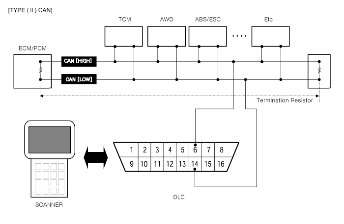
6) Communication Line (CAN)
| • |
Bus Topology : Line (bus) structure |
| • |
Wiring : Twisted pair wire |
| • |
Off Board DLC Cable Length : Max. 5m |
| • |
Data Transfer Rate |
| - |
Diagnostic : 500 kbps |
| - |
Service Mode (Upgrade, Writing VIN) : 500 or 1Mbps) |
7) Driving cycle
A driving cycle consists of engine start up, and engine shut off.
8) Warm-up cycle
A warm-up cycle means sufficient vehicle operation such that
the engine coolant temperature has risen by at least 40 degrees
Fahrenheit from engine starting and reaches a minimum temperature of at
least 160 degrees Fahrenheit.
9) DTC format
| • |
Diagnostic Trouble Code (SAE J2012) |
| • |
DTCs used in OBD-II vehicles will begin with a letter and are followed by four numbers. |
The letter of the beginning of the DTC identifies the
function of the monitored device that has failed. A "P" indicates a
powertrain device, "C" indicates a chassis device. "B" is for body
device and "U" indicates a network or data link code. The first number
indicates if the code is generic (common to all manufacturers) or if it
is manufacturer specific. A "0" & "2" indicates generic, "1"
indicates manufacturer-specific. The second number indicates the system
that is affected with a number between 1 and 7.
The following is a list showing what numbers are assigned to each system.
| • |
1 : Fuel and air metering |
| • |
2 : Fuel and air metering(injector circuit malfunction only) |
| • |
3 : Ignition system or misfire |
| • |
4 : Auxiliary emission controls |
| • |
5 : Vehicle speed controls and idle control system |
| • |
6 : Computer output circuits |
| • |
7 : Transmission |
The last two numbers of the DTC indicates the component or section of the system where the fault is located.
10) Freeze frame data
When a freeze frame event is triggered by an emission related
DTC, the ECM or PCM stores various vehicle information as it existed
the moment the fault ocurred. The DTC number along with the engine data
can be useful in aiding a technician in locating the cause of the fault.
Once the data from the 1st driving cycle DTC ocurrence is stored in the
freeze frame memory, it will remain there even when the fault ocurrs
again (2nd driving cycle) and the MIL is illuminated.
| • |
Freeze Frame List |
| 1) |
Calculated Load Value |
| 2) |
Engine RPM |
| 3) |
Fuel Trim |
| 4) |
Fuel Pressure (if available) |
| 5) |
Vehicle Speed (if available) |
| 6) |
Coolant Temperature |
| 7) |
Intake Manifold Pressure (if available) |
| 8) |
Closed-or Open-loop operation |
| 9) |
Fault code |
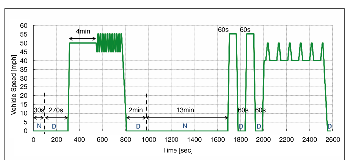
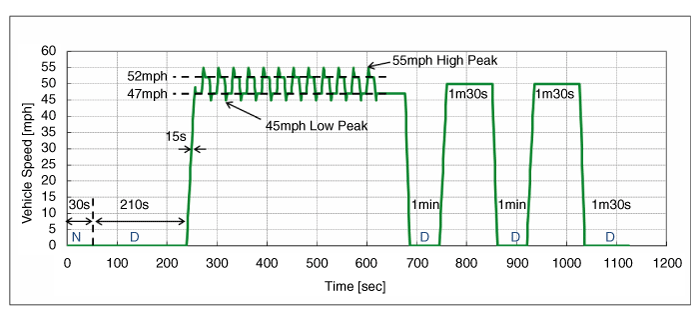
3. OBD-II Readiness Test
[Hyundai Drive Cycle]
Hyundai OBDII Drive Cycle is designed to execute and complete
the OBDII monitors. To complete a specific monitor for repair
verification, follow the Drive Cycle chart below.
Hyundai OBDII Drive Cycle consists of two modes (Mode 1 and
Mode 2) and the Mode 2 is to perform the catalyst diagnostics on Dephi
EMS only.
| - |
Continental, Bosch or Kefico EMS : Mode 1 drive cycle should be done one time for diagnostics on all systems. |
| - |
Dephi EMS : Mode 2 drive cycle should be done two times in a
row after Mode 1 is carried out one time for diagnostics on all systems |
| • |
Mode 1
|
| • |
Mode 2
|
| Mode | No | Operation | Speed (mph) | Duration (s) | E/Time (s) | Remarks |
| Mode 1 | 1 | Engine Start | 0 | 0 | 0 | ECT @ Start 32~104°F |
| 2 | Idling (N) | 0 | 30 | 30 | Neutral Range | |
| 3 | Idling (D) | 0 | 270 | 300 | D Range | |
| 4 | Acceleration | 0 > 50 | 15 | 315 | | |
| 5 | Steady Speed | 50 | 230 | 545 | | |
| 6 | Deceleration | 50 > 45 | 5 | 550 | | |
| 7 | Steady Speed | 45 | 5 | 555 | | |
| 8 | Acceleration | 45 > 55 | 5 | 560 | | |
| 9 | Steady Speed | 55 | 5 | 565 | | |
| 10 | Deceleration | 55 > 45 | 5 | 570 | | |
| 11 | Steady Speed | 45 | 5 | 575 | | |
| 12 | Repeat 8 through 11 ten times. | - | 180 | 755 | | |
| 13 | Acceleration | 45 > 55 | 5 | 760 | | |
| 14 | Steady Speed | 55 | 5 | 765 | | |
| 15 | Deceleration | 55 > 0 | 45 | 810 | | |
| 16 | Idling (D) | 0 | 120 | 930 | D Range | |
| 17 | Idling (N) | 0 | 760 | 1690 | Neutral Range | |
| 18 | Acceleration | 0 > 55 | 15 | 1705 | | |
| 19 | Steady Speed | 55 | 60 | 1765 | | |
| 20 | Deceleration | 55 > 0 | 15 | 1780 | | |
| 21 | Idling (D) | 0 | 60 | 1840 | D Range | |
| 22 | Acceleration | 0 > 55 | 15 | 1855 | | |
| 23 | Steady Speed | 55 | 60 | 1915 | | |
| 24 | Deceleration | 55 > 0 | 15 | 1930 | | |
| 25 | Idling (D) | 0 | 60 | 1990 | D Range | |
| 26 | Acceleration | 0 > 40 | 15 | 2005 | | |
| 27 | Steady Speed | 40 | 15 | 2020 | | |
| 28 | Acceleration | 40 > 50 | 15 | 2035 | | |
| 29 | Steady Speed | 50 | 5 | 2040 | | |
| 30 | Deceleration | 50 > 40 | 15 | 2055 | | |
| 31 | Steady Speed | 40 | 60 | 2115 | | |
| 32 | Repeat 28 through 31 five times. | - | 380 | 2495 | | |
| 33 | Acceleration | 40 > 50 | 15 | 2510 | | |
| 34 | Steady Speed | 50 | 5 | 2515 | | |
| Mode 1 | 35 | Deceleration | 50 > 0 | 40 | 2555 | |
| 36 | Idling (D) | 0 | 25 | 2580 | D Range | |
| Mode 2 | 1 | Engine Start | 0 | 0 | 0 | |
| 2 | Idling (N) | 0 | 30 | 30 | Neutral Range | |
| 3 | Idling (D) | 0 | 210 | 240 | D Range | |
| 4 | Acceleration | 0 > 49 | 16 | 256 | | |
| 5 | Deceleration | 49 > 47 | 2 | 258 | Lift Foot Up : APS = 0 | |
| 6 | Steady Speed | 47 | 10 | 268 | | |
| 7 | Acceleration | 47 > 55 | 4 | 272 | Middle Tip In or Deep Accel | |
| 8 | Deceleration | 55 > 52 | 3 | 275 | Lift Foot Up : APS = 0 | |
| 9 | Steady Speed | 52 | 10 | 285 | | |
| 10 | Deceleration | 52 > 45 | 3 | 288 | Lift Foot Up : APS = 0 | |
| 11 | Acceleration | 45 > 47 | 2 | 290 | | |
| 12 | Repeat 6 through 11 twelve times. | - | 330 | 620 | | |
| 13 | Steady Speed | 47 | 57 | 677 | | |
| 14 | Deceleration | 47 > 0 | 8 | 685 | | |
| 15 | Idling (D) | 0 | 60 | 745 | D Range | |
| 16 | Acceleration | 0 > 50 | 15 | 760 | | |
| 17 | Steady Speed | 50 | 90 | 850 | | |
| 18 | Deceleration | 50 > 0 | 10 | 860 | | |
| 19 | Repeat 15 through 18 two times. | - | 175 | 1035 | | |
| 20 | Idling (D) | 0 | 90 | 1125 | D Range |
1) Catalyst monitoring
The catalyst efficiency monitor is a self-test strategy
within the ECM or PCM that uses the downstream Heated Oxygen Sensor
(HO2S) to determine when a catalyst has fallen below the minimum level
of effectiveness in its ability to control exhaust emission.
2) Misfire monitoring
Misfire is defined as the lack of proper combustion in the
cylinder due to the absence of spark, poor fuel metering, or poor
compression. Any combustion that does not occur within the cylinder at
the proper time is also a misfire. The misfire detection monitor detects
fuel, ignition or mechanically induced misfires. The intent is to
protect the catalyst from permanent damage and to alert the customer of
an emission failure or an inspection maintenance failure by illuminating
the MIL . When a misfire is detected, special software called freeze
frame data is enabled. The freeze frame data captures the operational
state of the vehicle when a fault is detected from misfire detection
monitor strategy.
3) Fuel system monitoring
The fuel system monitor is a self-test strategy within the
ECM or PCM that monitors the adaptive fuel table The fuel control system
uses the adaptive fuel table to compensate for normal variability of
the fuel system components caused by wear or aging. During normal
vehicle operation, if the fuel system appears biased lean or rich, the
adaptive value table will shift the fuel delivery calculations to remove
bias.
4) Engine cooling system monitoring
The cooling system monitoring is a self-test strategy within
the ECM or PCM that monitors ECTS (Engine Coolant Temperature Sensor)
and thermostat about circuit continuity, output range, rationality
faults.
5) O2 sensor monitoring
OBD-II regulations require monitoring of the upstream Heated
O2 Sensor (H2OS) to detect if the deterioration of the sensor has
exceeded thresholds. An additional HO2S is located downstream of the
Warm-Up Three Way Catalytic Converter (WU-TWC) to determine the
efficiency of the catalyst.
Although the downstream H2OS is similar to the type used for
fuel control, it functions differently. The downstream HO2S is monitored
to determine if a voltage is generated. That voltage is compared to a
calibrated acceptable range.
6) Evaporative emission system monitoring
The EVAP. monitoring is a self-test strategy within the ECM
or PCM that tests the integrity of the EVAP. system. The complete
evaporative system detects a leak or leaks that cumulatively are greater
than or equal to a leak caused by a 0.040 inch and 0.020 inch diameter
orifice.
7) Air conditioning system monitoring
The A/C system monitoring is a self-test strategy within the
ECM or PCM that monitors malfunction of all A/C system components at A/C
ON.
8) Comprehensive components monitoring
The comprehensive components monitoring is a self-test
strategy within the ECM or PCM that detects fault of any electronic
powertrain components or system that provides input to the ECM or PCM
and is not exclusively an input to any other OBD-II monitor.
9) A/C system component monitoring
Requirement:
If a vehicle incorporates an engine control strategy that
alters off idle fuel and/or spark control when the A/C system is on, the
OBD II system shall monitor all electronic air conditioning system
components for malfunctions that cause the system to fail to invoke the
alternate control while the A/C system is on or cause the system to
invoke the alternate control while the A/C system is off.
Additionally, the OBD II system shall monitor for malfunction
all electronic air conditioning system components that are used as part
of the diagnostic strategy for any other monitored system or component.
Implementation plan:
No engine control strategy incorporated that alters offidle
fuel and/or spark control when A/C system is on. Malfuction of A/C
system components is not used as a part of the diagnostic strategy for
other monitored system or component.

 Components and Components Location
Components Location
1. Engine Control Module (ECM)2. Manifold Absolute Pressure Sensor (MAPS)3. Intake Air Temperature Sensor (IATS)4. Engine Coolant Temperature Sensor (ECTS)5. Throttle Positio ...
Other information:
Hyundai Tucson (LM) 2010-2015 Service Manual: Antenna Repair procedures
Inspection
Antenna Cable
1.
Remove the antenna jack from the audio unit and antenna.
2.
Check for continuity between the center poles of antenna cable.
3.
Check for continuity between the outer poles of antenna cable. There should be continuity.
4.
If there is no continuity, replace ...
Hyundai Tucson (LM) 2010-2015 Owners Manual: Manual climate control system
To defog inside windshield
1. Set the fan speed to the desired position.
2. Select the desired temperature.
3. Press the defrost button ( ).
4. The outside (fresh) air will be selected automatically. If the
position is selected, air conditioning
will also be selected automatically.
If the ...
© 2010-2026 www.htmanual.net
