Hyundai Tucson: Automatic Transaxle System / Automatic Transaxle Repair procedures
Hyundai Tucson (LM) 2010-2015 Service Manual / Automatic Transaxle System / Automatic Transaxle System / Automatic Transaxle Repair procedures
| Removal |
| 1. |
Remove the engine cover.
(Refer to Engine Mechanical System - "Engine cover") |
| 2. |
Remove the air cleaner assembly and air duct.
(Refer to Engine Mechanical System - "Air cleaner") |
| 3. |
Remove the battery and battery tray.
(Refer to Engine Electrical System - "Battery") |
| 4. |
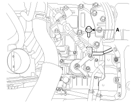
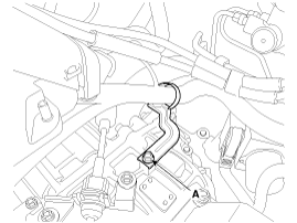
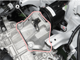
Remove the ground line after removing the bolt (A).
|
| 5. |
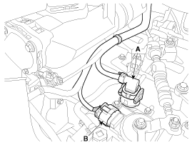
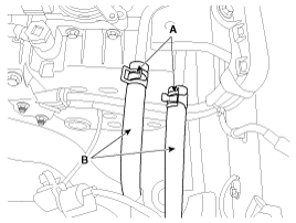
Dissconnect the solenoid valve connector (A) and inhibitor switch connector (B).
|
| 6. |
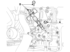
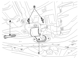
Remove the control cable (C) after removing the nut (A) and the bolt (B).
|
| 7. |
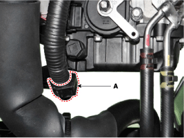
Disconnect the clip (A) from the automatic transaxle.
|
| 8. |
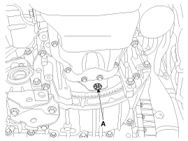
Remove the wiring mounting bracket bolt (A).
|
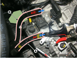
| 9. |
Disconnect the hose (B) after removing the automatic transaxle fluid cooler hose clamp (A).
|
| 10. |
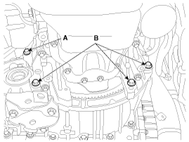
Remove the automatic transaxle upper mounting bolt (A-2ea) and the starter motor mounting bolt (B-2ea).
|
| 11. |
Remove the cowl top cover and wiper motor.
(Refer to Body Electrical System - "Windshield Wiper/Washer") |
| 12. |
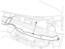
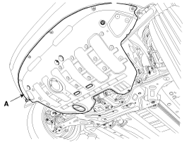
Remove the cowl complete assembly panel (A).
|
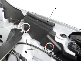
| 13. |
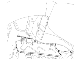
After loosening the mounting clips (A), then disconnect the fender side cover (B).
|
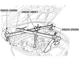
| 14. |
Using the engine support fixture (Support SST No.:
09200-2S000, Beam SST No.: 09200-38001), hold the engine and transaxle
assembly safely.
|
| 15. |
Remove the mounting bracket cover (A).
|
| 16. |
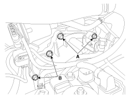
Remove the automatic transaxle mounting bracket bolt (A).
|
| 17. |
Remove the automatic transaxle mounting support bracket (A).
|
| 18. |
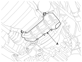
Remove the under cover (A).
|
| 19. |
Remove the side cover (A).
|
| 20. |
Remove the air guard (A) after removing the bolts.
|
| 21. |
Remove the following items;
2WD
4WD
|
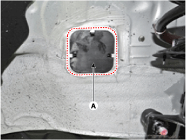
| 22. |
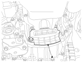
Remove the dust cover (A).
|
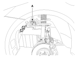
| 23. |
Remove the torque converter mounting bolt (A-4ea) with rotating the crankshaft.
|
| 24. |
Remove the automatic transaxle with a jack after removing the mounting bolt (A-1ea, B-3ea).
|
| Installation |
| 1. |
Install in the reverse order of removal.
|

| 2. |
In case of the reinstallation.
|

| 3. |
In case of the replacing with a new automatic transaxle.
|
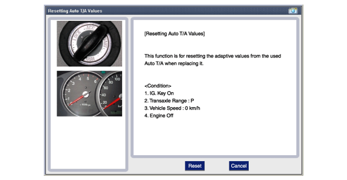
| 4. |
In case of the replacing with a remanufactured automatic transaxle.
|
 Automatic Transaxle Components and Components Location
Components Location
1. Automatic transaxle assembly2. Shift cable bracket3. Automatice transaxle mounting support bracket4. Rear cover5. Valve body cover6. Manual control lever7. Air breather hos ...
 Hydraulic System
...
Other information:
Hyundai Tucson (LM) 2010-2015 Service Manual: Intake Actuator Description and Operation
Description
1.
The intake actuator is located at the blower unit.
2.
It regulates the intake door by signal from control unit.
3.
Pressing the intake selection switch will shift between recirculation and fresh air modes.
...
Hyundai Tucson (LM) 2010-2015 Owners Manual: Seat belt safety precautions
Always fasten your seat belt and make sure all passengers have fastened their
seat belts before starting any trip. Air bags are designed to supplement the seat
belt as an additional safety device, but they are not a substitute. Most states
require all occupants of a vehicle to wear seat belts. ...
© 2010-2026 www.htmanual.net
