
Hyundai Tucson: Engine Control System / Engine Coolant Temperature Sensor (ECTS) Description and Operation
Hyundai Tucson (LM) 2010-2015 Service Manual / Engine Control / Fuel System / Engine Control System / Engine Coolant Temperature Sensor (ECTS) Description and Operation
| Description |
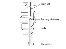
Engine Coolant Temperature Sensor (ECTS) is located in the
engine coolant passage of the cylinder head for detecting the engine
coolant temperature. The ECTS uses a thermistor that changes resistance
with the temperature.
The electrical resistance of the ECTS decreases as the
temperature increases, and increases as the temperature decreases. The
reference +5V is supplied to the ECTS via a resistor in the ECM. That
is, the resistor in the ECM and the thermistor in the ECTS are connected
in series. When the resistance value of the thermistor in the ECTS
changes according to the engine coolant temperature, the output voltage
also changes.
During cold engine operation, the ECM increases the fuel
injection duration and controls the ignition timing using the
information of engine coolant temperature to avoid engine stalling and
improve drivability.
 Intake Air Temperature Sensor (IATS) Repair procedures
Inspection
1.
Turn the ignition switch OFF.
2.
Disconnect the IATS connector.
3.
Measure resistance between the IATS terminals 3 and 4.
4.
Check that the resistance is within the speci ...
 Engine Coolant Temperature Sensor (ECTS) Specifications
Specification
TemperatureResistance (kx)°C°F-40-4048.14-20-414.13 ~ 16.830325.7920682.31 ~ 2.59401041.15601400.59801760.32
...
Other information:
Hyundai Tucson (LM) 2010-2015 Service Manual: Alternator Schematic Diagrams
Circuit Diagram
•
COM signal - When
controlling the voltage generated, the ECM sends the target voltage data
to the alternator via a PWM signal.(High voltage: 4V or higher, low
voltage: 2V or lower)
•
FR signal - The
transistor activation signal inside t ...
Hyundai Tucson (LM) 2010-2015 Owners Manual: Tire rotation
To equalize tread wear, HYUNDAI recommends that the tires be rotated every 7,500
miles (12,000 km) or sooner if irregular wear develops. During rotation, check the
tires for correct balance.
When rotating tires, check for uneven wear and damage. Abnormal wear is usually
caused by incorrect ti ...
© 2010-2026 www.htmanual.net
