Hyundai Tucson: Installing a Child Restraint System (CRS) / Lower Anchors and Tether for Children (LATCH) System
The LATCH system holds a child restraint during driving and in an accident.
This system is designed to make installation of the child restraint easier and reduce the possibility of improperly installing your child restraint. The LATCH system uses anchors in the vehicle and attachments on the child restraint. The LATCH system eliminates the need to use seat belts to secure the child restraint to the rear seats.
Lower anchors are metal bars built into the vehicle. There are two lower anchors for each LATCH seating position that will accommodate a child restraint with lower attachments.
To use the LATCH system in your vehicle, you must have a child restraint with LATCH attachments.
The child seat manufacturer will provide you with instructions on how to use the child seat with its attachments for the LATCH lower anchors.
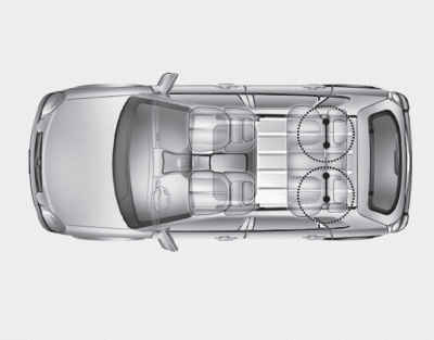
LATCH anchors have been provided in the left and right outboard rear seating positions. Their locations are shown in the illustration. There are no LATCH anchors provided for the center rear seating position.
WARNING
Do not attempt to install a child restraint system using LATCH anchors in the rear center seating position.There are no LATCH anchors provided for this seat. Using the outboard seat anchors can damage the anchors which may break or fail in a collision resulting in serious injury or death.
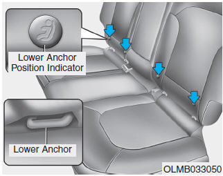
The lower anchor position indicator symbols are located on the left and right rear seat backs to identify the position of the lower anchors in your vehicle (see arrows in illustration).
The LATCH anchors are located between the seatback and the seat cushion of the rear seat left and right outboard seating positions.
 Installing a Child Restraint System (CRS)
WARNING
Before installing your child restraint system always:
Read and follow the instructions provided by the manufacturer of the
child restraint.
Read and follow the instructions regarding ...
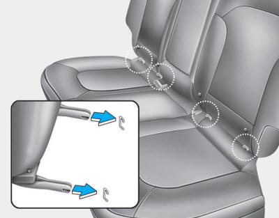
 Securing a child restraint with the LATCH anchors system
To install a LATCH-compatible child restraint in either of the rear outboard
seating positions:
1. Move the seat belt buckle away from the lower anchors.
2. Move any other objects away from the an ...
Other information:
Hyundai Tucson (LM) 2010-2015 Service Manual: Manifold Absolute Pressure Sensor (MAPS) Repair procedures
Inspection
1.
Connect the GDS on the Data Link Connector (DLC).
2.
Measure the output voltage of the MAPS at idle and IG ON.
Specification: Refer to "Specification"
Removal
1.
Turn the ignition switch OFF and disconnect the battery negative (-) cable.
2.
Disconnect the manif ...
Hyundai Tucson (LM) 2010-2015 Service Manual: Description and Operation
Description
The immobilizer system will disable the vehicle unless the
proper ignition key is used, in addition to the currently available
anti-theft systems such as car alarms, the immobilizer system aims to
drastically reduce the rate of auto theft.
1.
Encrypted SMARTRA type immobilizer ...
