Hyundai Tucson: Seat belt restraint system / Pre-tensioner seat belt
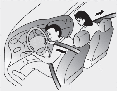
Your vehicle is equipped with driver's and front passenger's Pre-Tensioner Seat Belts. The purpose of the pretensioner is to make sure the seat belts fit tightly against the occupant's body in certain frontal collisions. The pre-tensioner seat belts may be activated in crashes where the frontal collision is severe enough.

When the vehicle stops suddenly, or if the occupant tries to lean forward too quickly, the seat belt retractor will lock into position. In certain frontal collisions, the pre-tensioner will activate and pull the seat belt into tighter contact against the occupant's body.
If the system senses excessive tension on the driverŌĆÖs or passenger's seat belt when the pre-tensioner activates, the load limiter inside the pretensioner will release some of the pressure on the affected seat belt.
WARNING
Pre-Tensioner Seat Belts that malfunction may not protect you properly during an accident. Take the following precautions:
- Always wear your seat belt and sit properly in your seat.
- Do not use the seat belt if it is loose or twisted. A loose or twisted seat belt will not protect you properly in an accident.
- Do not place anything near the buckle. This may adversely affect the buckle and cause it to function improperly.
- Always replace your pre-tensioners after activation or an accident.
- NEVER inspect, service, repair or replace the pre-tensioners yourself. This must be done by an authorized HYUNDAI dealer.
- Do not hit the seat belt assemblies.
WARNING
Do not touch the pre-tensioner seat belt assemblies for several minutes after they have been activated. When the pre-tensioner seat belt mechanism fires during a collision the pretensioner becomes hot and can burn you.

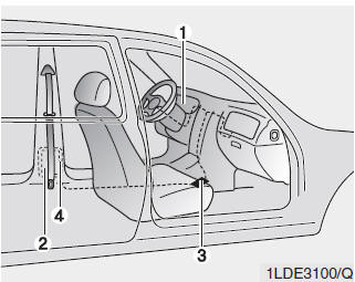
The Pre-Tensioner Seat Belt System consists mainly of the following components.
Their locations are shown in the illustration above:
1. SRS air bag warning light
2. Retractor pre-tensioner assembly
3. SRS control module
4. Anchor pre-tensioner assembly
Ō£Į NOTICE
The sensor that activates the SRS air bag is connected with the preŌĆōtensioner seat belts. The SRS air bag warning light on the instrument panel will illuminate for approximately 6 seconds after the ignition switch is placed in the ON position, and then it should turn off. If the pre-tensioner is not working properly, the warning light will illuminate even if the SRS air bag is not malfunctioning. If the warning light does not illuminate, stays illuminated or illuminates when the vehicle is being driven, have an authorized HYUNDAI dealer inspect the pretensioner seat belts and SRS air bags as soon as possible.
Ō£Į NOTICE
- Both the driver's and front passenger's pre-tensioner seat belts may be activated in certain frontal or side collisions or rollovers.
- The pre-tensioners will not be activated if the seat belts are not worn at the time of the collision.
- When the pre-tensioner seat belts are activated, a loud noise may be heard and fine dust, which may appear to be smoke, may be visible in the passenger compartment. These are normal operating conditions and are not hazardous.
- Although it is non-toxic, the fine dust may cause skin irritation and should not be breathed for prolonged periods. Wash all exposed skin areas thoroughly after an accident in which the pre-tensioner seat belts were activated.
 Seat Belt ŌĆō PassengerŌĆÖs 3-point system with combination locking retractor
This type of seat belt combines the features of both an emergency locking retractor
seat belt and an automatic locking retractor seat belt.
Combination retractor type seat belts are installed in th ...
 3-point rear center seat belt
To fasten the rear center seat belt:
1. Extract the metal tab from the hole of the belt assembly cover and slowly
pull the metal tab out from the retractor.
2. Insert the metal tab (A) into th ...
Other information:
Hyundai Tucson (LM) 2010-2015 Owners Manual: Electronic Stability Control (ESC)
The Electronic Stability Control (ESC) system helps to stabilize the vehicle
during cornering maneuvers.
ESC checks where you are steering and where the vehicle is actually going. ESC
applies braking pressure to any one of the vehicleŌĆÖs brakes and intervenes in the
engine management sys ...
Hyundai Tucson (LM) 2010-2015 Owners Manual: Rear window defroster
The defroster heats the window to help remove frost, fog and thin ice from the
rear window, while the engine is running.
To activate the rear window defroster, press the rear window defroster button
located in the center facia switch panel. The indicator on the rear window defroster
butto ...
