
Hyundai Tucson: Heating and air conditioning / Mode selection
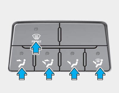
The mode selection button controls the direction of the air flow through the ventilation system.
Air can be directed to the floor, dashboard outlets, or windshield. Six symbols are used to represent the direction and flow of ventilation: MAX A/C, Face, Bi-Level, Floor, Floor- Defrost and Defrost air position.
MAX A/C-Level (B, D)

Air flow is directed toward the upper body and face. The MAX A/C mode is used to cool the inside of the vehicle faster.
In this mode, the air conditioning and the recirculated air position will be selected automatically.
Face-Level (B, D)

Air flow is directed toward the upper body and face. Additionally, each outlet can be controlled to direct the air discharged from the outlet.
Bi-Level (B, D, E, C)

Air flow is directed towards the face and the floor.
Floor-Level (C, A, D, E)

Most of the air flow is directed to the floor, with a small amount of the air being directed to the windshield and side window defrosters.
Floor/Defrost-Level (A, C, D, E)

Most of the air flow is directed to the floor and the windshield with a small amount directed to the side window defrosters.
Defrost-Level (A, D)

Most of the air flow is directed to the windshield with a small amount of air directed to the side window defrosters.
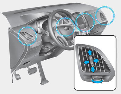
Instrument panel vents
The outlet vents can be opened or closed separately using the horizontal thumbwheel. To close the vent, rotate it left to the maximum position. To open the vent, rotate it right to the desired position.
Also, you can adjust the direction of air delivery from these vents using the vent control lever as shown.
 Heating and air conditioning
1. Start the engine.
2. Set the mode to the desired position.
To improve the effectiveness of heating and cooling;
- Heating:
- Cooling:
3. Set the temperature control to the desired position.
...
 Temperature control
The temperature control knob allows you to control the temperature of the air
flowing from the ventilation system.
To change the air temperature in the passenger compartment, turn the knob to
...
Other information:
Hyundai Tucson (LM) 2010-2015 Owners Manual: All wheel drive (AWD)
The All Wheel Drive (AWD) System delivers engine power to all front and rear
wheels for maximum traction.
AWD is useful when extra traction is required on roads such slippery, muddy,
wet, or snow-covered roads.
Occasional off-road use such as established unpaved roads and trails are OK.
It i ...
Hyundai Tucson (LM) 2010-2015 Service Manual: Accelerator Position Sensor (APS) Repair procedures
Inspection
1.
Connect the GDS on the Data Link Connector (DLC).
2.
Turn the ignition switch ON.
3.
Measure the output voltage of the APS 1 and 2 at C.T and W.O.T.
Specification: Refer to “Specification�
Removal
1.
Turn the ignition switch OFF and disconnect the negative ...
