Hyundai Tucson: Differential Carrier Assembly / Rear Differential Carrier Repair procedures
Hyundai Tucson (LM) 2010-2015 Service Manual / Driveshaft and axle / Differential Carrier Assembly / Rear Differential Carrier Repair procedures
| Replacement |
| 1. |
Drain the differential gear oil. |
| 2. |
Remove the rear drive shaft. |
| 3. |
Remove the propeller shaft. |
| 4. |
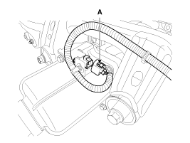
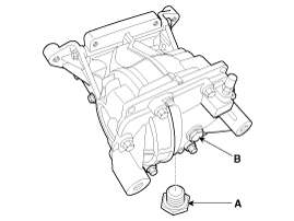
Disconnect the coupling control connector (A).
|
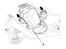
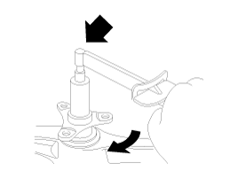
| 5. |
Support the differential assembly (A) with the jack (B).
|
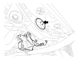
| 6. |
After loosen the cover bolt and then remove the differential cover (A).
|
| 7. |
Install in the reverse order of removal. |
| Disassembly |
Rear differential carrier disassembly
| 1. |
Drain oil by removing the drain plug (A) and pillar plug (B) before disassembling the rear differential carrier.
|

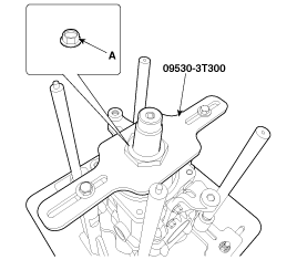
| 2. |
Using the SST (09530-3T300), hold the differential assembly safely.
|
| 3. |
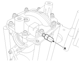
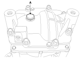
Remove the air breather plug (A).
|
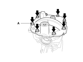
| 4. |
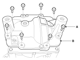
Loosen the cover bolts (A-8EA) and then remove the cover (B).
|
| 5. |
Loosen the bolts (A-4EA) and then remove the bearing cap (B).
|
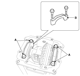
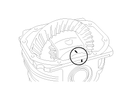
| 6. |
Remove the gear carrier assembly (A).
|
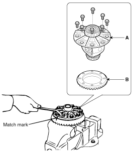
| 7. |
Mark the left and right side bearing race as below when removing the differential assembly to distinguish the sides.
|
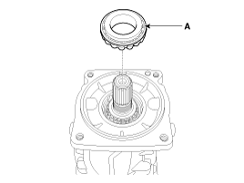
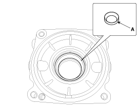
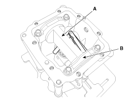
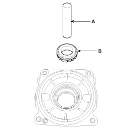
| 8. |
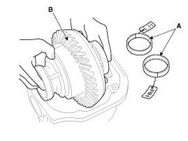
Using the screwdriver, remove the left and right side oil seal (A).
|
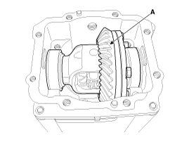
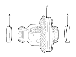
Gear carrier assembly disassembly
| 1. |
Loosen the seal bolts and then remove the gear carrier (A) and ring gear (B).
|

| 2. |
Using the SST (09530-3T200) remove the front and rear bearing (A).
|
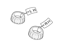
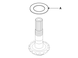
| 3. |
Mark the left and right side bearing as below when removing the bearing to distinguish the sides.
|
disassembly the pinion assembly
| 1. |
Using the SST (09530-3T300), fix the differential carrier assembly.
|
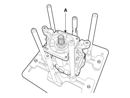
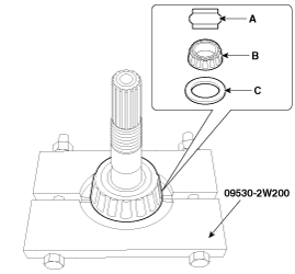
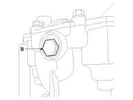
| 2. |
Fix the SST (09530-2W300) on the lock nut.
|
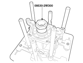
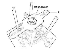
| 3. |
Fix the flange fix (A) on the SST (095302W300).
|
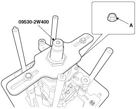
| 4. |
Insert the SST (095302W400) to the hole of the hexagon and then remove the lock nut (A).
|
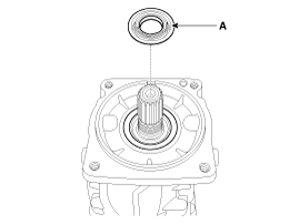
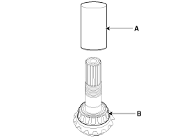
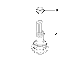
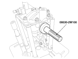
| 5. |
Using the screwdriver, remove the pinion oil seal (A).
|
| 6. |
Press the drive gear and remove the pinion front bearing (A).
|
| 7. |
Using a hammer and chisel, remove the pinion bearing outer race (A).
|
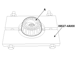
| 8. |
Using the SST (09527-4A000), press the pinion drive gear and
then remove the pinion bearing spacer (A), the front bearing (B), Inner
bearing adjustment shims (C) in the order.
|
| Reassembly |
Pinion drive gear height adjustment
Adjust the height of the drive pinion in the following order.
| 1. |
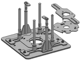
Below are the special tools to measure the pinion height
|
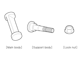
| 2. |
The special tool lock nut (A), pinion oil seal (B), pinion
front bearing (C), inner bearing (D) and special tool support body (E)
are mounted as follows.
|
| 3. |
Put the main body (A) on the Differential Case (B).
|
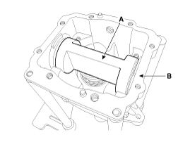
| 4. |
The bearing cap (B) is mounted on the main body (A).
|
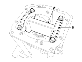
| 5. |
Using the feeler gage, measure the gap between the main body
(A) and bearing cap (B). and then select the inner bearing adjustment
shim.
|
| 6. |
Install the selected inner bearing (A) adjustment shim.
Inner bearing adjustment shim
|
Rear differential carrier reassembly
| 1. |
Using the SST (09530-3T100), install the inner pinion bearing outer race (A).
|
| 2. |
Using the SST (09530-3T100), install the outer pinion bearing outer race.
|
| 3. |
Using the round pipe (A), press in the pinion rear bearing (B).
|
| 4. |
Install the pinion bearing spacer (B) on the pinion drive gear (A).
|
| 5. |
Using the round pipe (A), press the front bearing (B).
|
| 6. |
Using the SST (09530-3T600), install the pinion oil seal.
|
| 7. |
Using the SST (09530-3T300), tighten the pinion lock nut (A).
|
| 8. |
Measure the Preload.
|
|
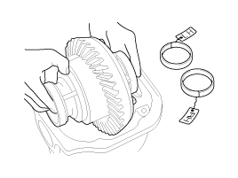
Gear carrier assembly reassembly
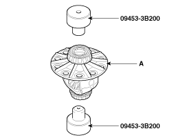
| 1. |
Using the SST (09453-3B200), install the front/rear bearing (A).
|
| 2. |
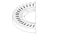
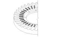
Install the gear carrier and ring gear.
|
| 3. |
Install the left and right side bearing outer race (A) to the gear carrier.
|
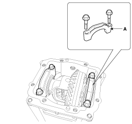
| 4. |
Fix the left and right side bearing outer race (A) with both hands and install it on the differential case.
|
| 5. |
Insert the left and right adjustment spacer between the
differential side bearing and carrier. And than install the baearing cap
(A) with mark.
|
| 6. |
Adjust the differential shim and confirm the standard of the backrash.
|
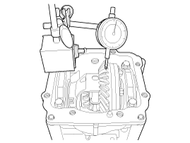
| 7. |
Adjust gear assembly run out backrash.
|
| 8. |
Measures the freeroad.
|
| 9. |
Coat sealant (A) on the rear cover surface.
|
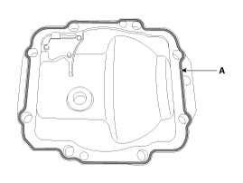
| 10. |
Install the differential rear cover (A).
|
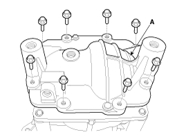
| 11. |
Install the drain plug (A) and pillar plug (B).
|
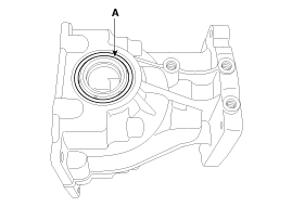
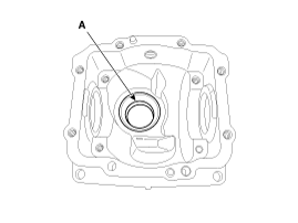
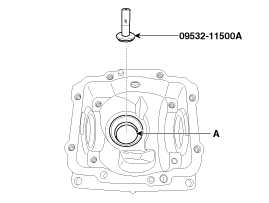
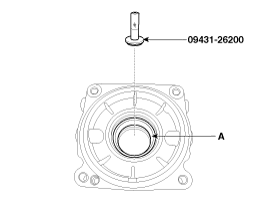
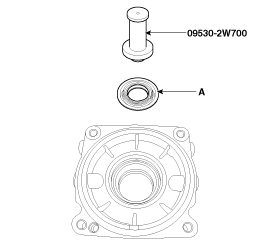
| 12. |
Using the SST(09530-3T000), install the left and right side oil seal.
|
| 13. |
Reassemble the rear differential assembly to the vehicle and inject oil.
|
| Inspection |
| 1. |
After clearing, check for damage parts or abrasion. Follow the below method, if any are noticed.
| ||||||||||||||||||||||||||
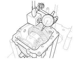
| 2. |
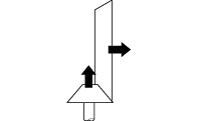
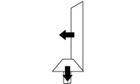
Check the tooth contact pattern.
| ||||||||||||||||||||||||||||


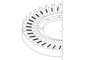
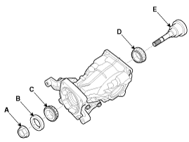
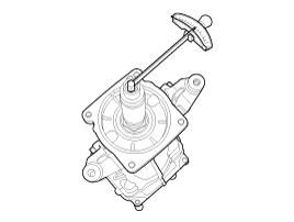
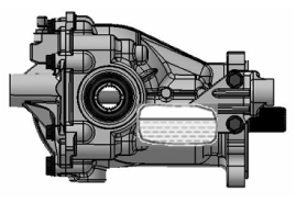
 Rear Differential Carrier Components and Components Location
Components Location
1. Rear Differential Carrier2. Coupling Assembly
Components
1. Pinion lock nut2. Pinion oil seal3. Pinion front bearing4. Differential case bracket5. Differential case6. ...

Other information:
Hyundai Tucson (LM) 2010-2015 Service Manual: CVVT Oil Control Valve (OCV) Schematic Diagrams
Circuit Diagram
(M/T)
(A/T)
...
Hyundai Tucson (LM) 2010-2015 Service Manual: Rheostat Repair procedures
Inspection
1.
Disconnect the negative (-) battery terminal.
2.
Remove the crash pad lower panel.
(Refer to the BD group - "Crash pad")
3.
Remove the crash pad side switch assembly (A) as shown below picture.
Put on gloves to protect your hands.
4.
Remove th ...
© 2010-2026 www.htmanual.net
