Hyundai Tucson: Starting System / Starter Repair procedures
Hyundai Tucson (LM) 2010-2015 Service Manual / Engine Electrical System / Starting System / Starter Repair procedures
| Removal |
| 1. |
Disconnect the battery negative terminal. |
| 2. |
Remove the air duct and air cleaner assembly.
(Refer to Engine Mechanical System - "Air Cleaner") |
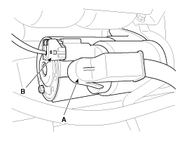
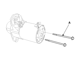
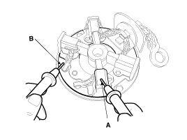
| 3. |
Disconnect the starter cable (A) from the B terminal on the solenoid then disconnect the connector from the S terminal (B).
|
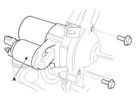
| 4. |
Remove the 2 bolts holding the starter, then remove the starter (A).
|
| Installation |
| 1. |
Install in the reverse order of removal.
|
| Disassembly |
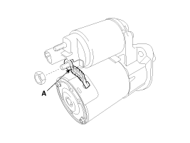
| 1. |
Disconnect the M-terminal (A) on the magnet switch assembly.
|
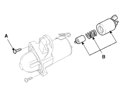
| 2. |
After loosening the screws (A), detach the magnet switch ssembly (B).
|
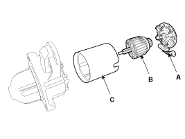
| 3. |
Loosen the through bolts (A).
|
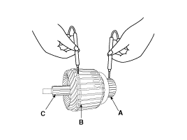
| 4. |
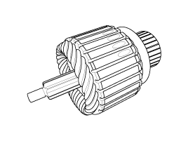
Remove the brush holder assembly (A), armature assembly (B) and yoke assembly (C).
|
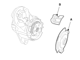
| 5. |
Remove the gasket sheet (A) and lever stop (B).
|
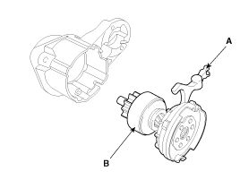
| 6. |
Remove the reducer assembly (A) and lever (B).
|
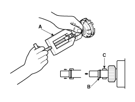
| 7. |
Press the stopper (A) using a socket (B).
|
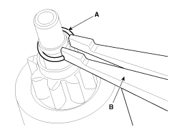
| 8. |
After removing the stop ring (A) using stop ring pliers (B).
|
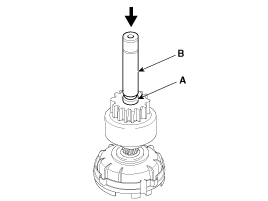
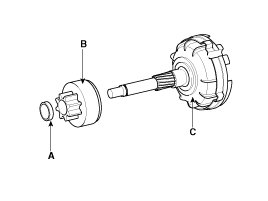
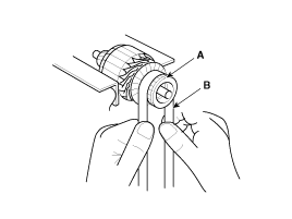
| 9. |
Disconnect the stopper (A), overrunning clutch (B) and internal gear (C).
|

| 10. |
Reassembly is the reverse of disassembly. |
| Reassembly |
| 1. |
Reassemble in the reverse order of disassembly. |
| Inspection |
| Starter Solenoid Inspection |
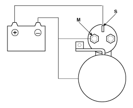
| 1. |
Disconnect the lead wire from the M-terminal of solenoid switch. |
| 2. |
Connect the battery as shown. If the starter pinion pops out, it is working properly.
|
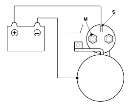
| 3. |
Disconnect the battery from the M terminal.
If the pinion does not retract, the hold-in coil is working properly.
|
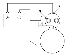
| 4. |
Disconnect the battery also from the body. If the pinion retracts immediately, it is working properly.
|
| Free Running Inspection |
| 1. |
Place the starter motor in a vise equipped with soft jaws and
connect a fully-charged 12-volt battery to starter motor as follows. |
| 2. |
Connect a test ammeter (150-ampere scale) and carbon pile rheostats shown is the illustration. |
| 3. |
Connect a voltmeter (15-volt scale) across starter motor.
|
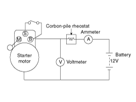
| 4. |
Rotate carbon pile to the off position. |
| 5. |
Connect the battery cable from battery's negative post to the starter motor body. |
| 6. |
Adjust until battery voltage shown on the voltmeter reads 11volts. |
| 7. |
Confirm that the maximum amperage is within the specifications and that the starter motor turns smoothly and freely.
|
Armature Inspection And Test
| 1. |
Remove the starter. |
| 2. |
Disassemble the starter as shown at the beginning of this procedure. |
| 3. |
Inspect the armature for wear or damage from contact with the
permanent magnet. If there is wear or damage, replace the armature.
|
| 4. |
Check the commutator (A) surface. If the surface is dirty or
burnt, resurface with emery cloth or a lathe within the following
specifications, or recondition with #500 or #600 sandpaper (B).
|
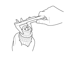
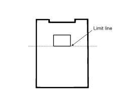
| 5. |
Check the commutator diameter. If the diameter is below the service limit, replace the armature.
|
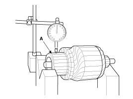
| 6. |
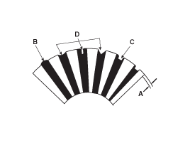
Measure the commutator (A) runout.
|
| 7. |
Check the mica depth (A). If the mica is too high (B),
undercut the mica with a hacksaw blade to the proper depth. Cut away all
the mica (C) between the commutator segments. The undercut should not
be too shallow, too narrow, or v-shaped (D).
|
| 8. |
Check for continuity between the segments of the commutator.
If an open circuit exists between any segments, replace the armature.
|
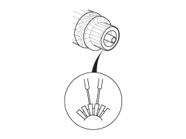
| 9. |
Check with an ohmmeter that no continuity exists between the
commutator (A) and armature coil core (B), and between the commutator
and armature shaft (C). If continuity exists, replace the armature.
|
Inspect Starter Brush
Brushes that are worm out, or oil-soaked, should be replaced.
Starter Brush Holder Test
Make sure there is no continuity between the (+) brush holder
(A) and (-) plate (B). If there is continuity, replace the brush holder
assembly.
Overrunning Clutch
| 1. |
Slide the overrunning clutch along the shaft.
Replace it if does not slide smoothly. |
| 2. |
Rotate the overrunning clutch both ways.
Does it lock in one direction and rotate smoothly in reversex
If it does not lock in either direction or it locks in both directions,
replace it.
|
| 3. |
If the starter drive gear is worn or damaged, replace the overrunning clutch assembly. (the gear is not available separately).
Check the condition of the flywheel or torque converter ring gear if the starter drive gear teeth are damaged. |
| Cleaning |
| 1. |
Do not immerse parts in cleaning solvent.
Immersing the yoke assembly and/or armature will damage the insulation wipe these parts with a cloth only. |
| 2. |
Do not immerse the drive unit in cleaning solvent.
The overrun clutch is pre-lubricated at the factory and sol-vent will wash lubrication from the clutch. |
| 3. |
The drive unit may be cleaned with a brush moistened with cleaning solvent and wiped dry with a cloth. |
 Starter Schematic Diagrams
Circuit Diagram
...
 Starter Relay Repair procedures
Inspection
1.
Disconnect the battery negative terminal.
2.
Remove the fuse box cover.
3.
Remove the starter relay (A).
4.
Using an ohmmeter, check that there is continuity between each ...
Other information:
Hyundai Tucson (LM) 2010-2015 Service Manual: Heated Oxygen Sensor (HO2S) Specifications
Specification
HO2S [Bank 1/Sensor 1] (Linear type)
ItemSpecificationHeater Resistance (x)2.4 ~ 4.0 [20°C(68°F)]
HO2S [Bank 1/Sensor 2] (Binary type)
A/F Ratio (x)Output Voltage(V)RICH0.6 ~ 1.0LEAN0 ~ 0.4
ItemSpecificationHeater Resistance (x)Approx. 9.0 [20°C(68°F)]
...
Hyundai Tucson (LM) 2010-2015 Service Manual: 35R Clutch Control Solenoid Valve(35R/C_VFS) Specifications
Specifications
Direct control VFS[35R/C]
x Control type : Normal high type
Control Pressure kpa (kgf/cmx, psi) 500.14 ~ 9.81(5.1 ~ 0.1, 72.54 ~ 1.42)Current value(mA)50 ~ 850 Internal resistance(x)5.1
...
© 2010-2026 www.htmanual.net
