Hyundai Tucson: Evaporative Emission Control System / Canister Repair procedures
Hyundai Tucson (LM) 2010-2015 Service Manual / Emission Control System / Evaporative Emission Control System / Canister Repair procedures
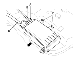
| Removal |
| 1. |
Remove the fuel tank.
(Refer to "Fuel tank" in FL group.) |
| 2. |
Disconnect the vapor tube quick-connector (A,B) and the ventilation hose (C). |
| 3. |
Remove the canister in the direction of an arrow after removing the installation screws (D).
|
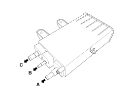
| Inspection |
| 1. |
Check for the following items visually.
- Cracks or leakage of the canister
- Loose connection, distortion, or damage of the vapor hose/tube
A: Canister - Atmosphere
B: Canister - Intake Manifold
C: Canister - Fuel Tank
|
| Installation |
Install in the reverse order of removal.
Canister installation bolt/nut:
3.9 ~ 5.9 N.m (0.4 ~ 0.6 kgf.m, 2.9 ~ 4.3 lb-ft) |
 Repair procedures
Inspection
[EVAP. Leakage Test]
1.
Select "Evap. Leakage Test".
2.
Proceed with the test according to the screen introductions. ...
 Fuel Filler Cap Description and Operation
Description
A ratchet tightening device on the threaded fuel filler cap
reduces the chances of incorrect installation, which seals the fuel
filler. After the gasket on the fuel filler cap and t ...
Other information:
Hyundai Tucson (LM) 2010-2015 Service Manual: Smart Parking Assist System Speaker Repair procedures
Removal
1.
Disconnect the negative (-) battery terminal.
2.
Remove the crash pad lower panel.
(Refer to the BD group - "Crash pad")
3.
Remove the SPAS speaker (A) after disconnecting the connector and removing the nut.
Installation
1.
Install the SPAS speaker and crash pad lower pa ...
Hyundai Tucson (LM) 2010-2015 Owners Manual: Fan speed control
The fan speed can be set to the desired speed by operating the fan speed control
switches.
To change the fan speed, press the (
) the switch for higher speed, or press
the ( ) switch for lower speed. To
turn the fan speed control off, press the front blower OFF button. ...
© 2010-2026 www.htmanual.net
