
Hyundai Tucson: Indicators And Gauges / Instrument Cluster Schematic Diagrams
Hyundai Tucson (LM) 2010-2015 Service Manual / Body Electrical System / Indicators And Gauges / Instrument Cluster Schematic Diagrams
| Circuit Diagram (1) |
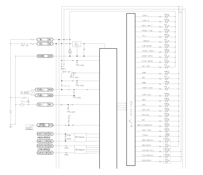
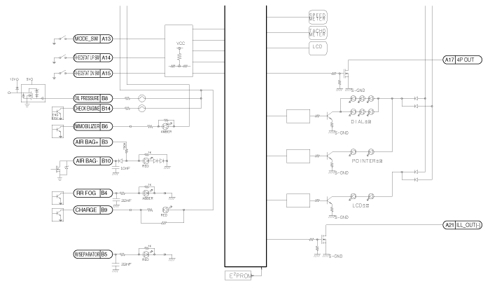
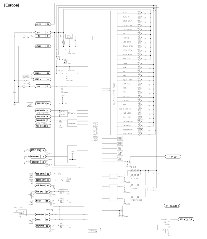
| Circuit Diagram (2) |
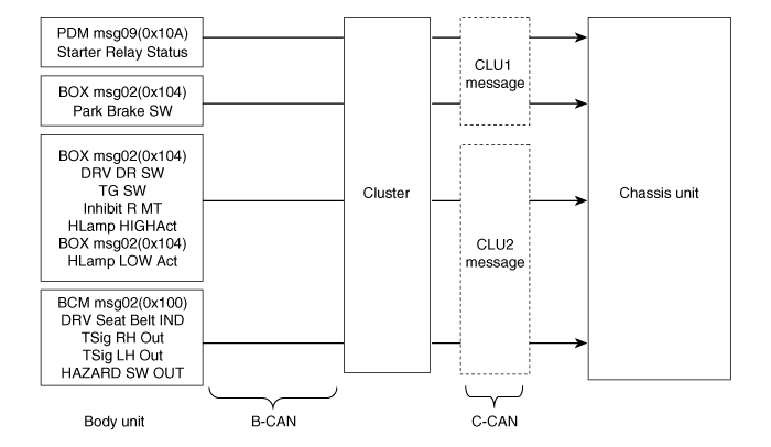
| Massage Flow Diagram |
 Instrument Cluster Components and Components Location
Components (1)
Components (2)
...
 Instrument Cluster Description and Operation
Description
ECO driving system
This system is designed to encourage eco-driving by providing real-time feedback to the driver.
The ECO indicator light assists you to drive in the most economical ...
Other information:
Hyundai Tucson (LM) 2010-2015 Owners Manual: AWD LOCK indicator (if equipped)
The AWD LOCK indicator light is illuminated when the AWD LOCK button is pushed.
The purpose of this AWD LOCK mode is to increase the drive power when driving on
wet pavement, snow-covered roads and/or off-road.The AWD LOCK indicator light is
turned off by pushing the button again.
CAUTION
...
Hyundai Tucson (LM) 2010-2015 Service Manual: Camshaft Repair procedures
Removal
Timing chain cover removal is not required for this procedure.
•
Use fender covers to avoid damaging painted surfaces.
•
To avoid damage, unplug the wiring connectors carefully while holding the connector portion.
•
Mar ...
© 2010-2026 www.htmanual.net
