Hyundai Tucson: Fuses And Relays / PDM Relay Box Repair procedures
| Inspection |
| 1. |
Disconnect the negative (-) battery terminal. |
| 2. |
Remove the front seat heater switch.
(Refer to BE group - "Seat heater switch") |
| 3. |
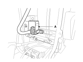
Remove the PDM relay box (A) after loosening the screws (2EA) and desconnecting the connector.
|
| 1. |
There should be continuity between the No.1 in the B and No.2
in the B terminals when power and ground are connected to the No.3 in
the A and No.4 terminals in the A terminals. |
| 2. |
There should be no continuity between the No.1 in the B and No.2 terminals in the B terminals when power is disconnected. |
| 1. |
There should be continuity between the No.7 in the A and No.8
in the A terminals when power and ground are connected to the No.3 in
the A and No.10 terminals in the A terminals. |
| 2. |
There should be no continuity between the No.7 in the A and No.8 terminals in the A terminals when power is disconnected. |
| 1. |
There should be continuity between the No.7 in the A and No.6
in the A terminals when power and ground are connected to the No.1 in
the A and No.3 terminals in the A terminals. |
| 2. |
There should be no continuity between the No.7 in the A and No.6 terminals in the A terminals when power is disconnected. |
 PDM Relay Box Description and Operation
Description
The PDM relay is united with IG1, IG2 and ACC relays and installed beside the assist instrument panel. ...
Other information:
Hyundai Tucson (LM) 2010-2015 Owners Manual: How does the air bags system operate?
The SRS consists of the following components:
1. Driver's front air bag module
2. Passenger's front air bag module
3. Side impact air bag modules
4. Curtain air bag modules
5. Retractor pre-tensioner assemblies
6. Air bag warning light
7. SRS control module (SRSCM)/ Rollover sensor
8. Fron ...
Hyundai Tucson (LM) 2010-2015 Service Manual: Back-up Lamp Switch Repair procedures
Inspection
1.
Disconnect the back up lamp switch connector (A).
2.
Check the continuity between no. 1 and 2 terminals of backup
lamp switch. When the shift lever is in reverse, there should be
continuity.
3.
If necessary, repair or replace the backup lamp switch.
Replacement
1. ...


